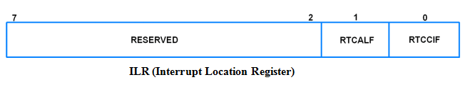
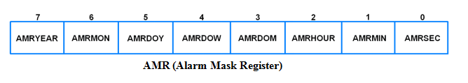
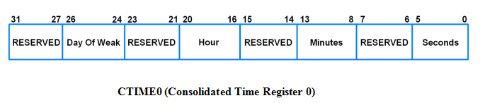
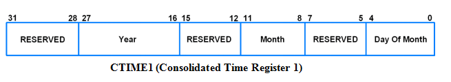
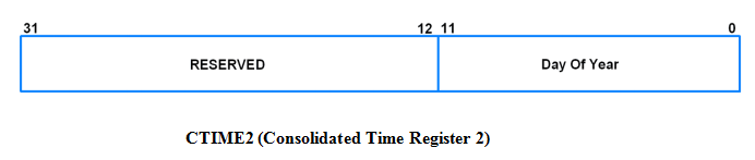
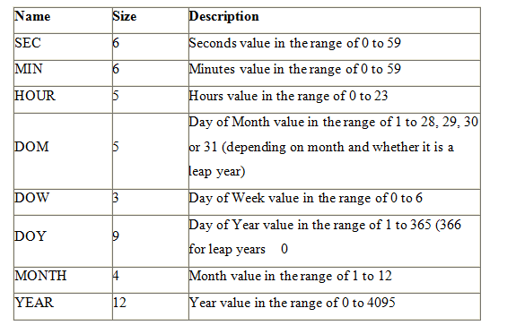
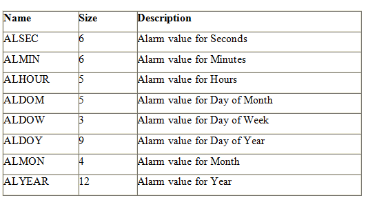
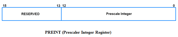
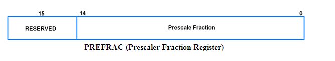
RTC INTERFACING WITH ARM
 A real-time clock (RTC) is a computer clock (most often in the form of an integrated circuit) that keeps track of the current time. Although the term often refers to the devices in personal computers, servers and embedded systems, RTCs are present in almost any electronic device which needs to keep accurate time. It demonstrates the principle behind the interfacing of RTC with ARM LPC2148.
Synopsis

 A real-time clock (RTC) is a computer clock (most often in the form of an integrated circuit) that keeps track of the current time. Although the term often refers to the devices in personal computers, servers and embedded systems, RTCs are present in almost any electronic device which needs to keep accurate time. It demonstrates the principle behind the interfacing of RTC with ARM LPC2148. A better, cost-effective alternative is to implement the RTC functionality into a microcontroller ARM LPC2148 that performs other useful tasks as well. RTC is used even when the system is not in operation. This is the system used in many devices including Laptop. Mobile phones, Tablet, Digital Cameras etc. RTC is inbuilt part of any electronics device.

Description

ARM is one of the major options available for embedded system developer. LPC2148 is the widely used IC from ARM-7 family. It is manufactured by Philips and it is pre-loaded with many inbuilt peripherals making it more efficient and a reliable option for the beginners as well as high end application developer.

ARM is a family of instruction set architectures for computer processors based on a reduced instruction set computing (RISC) architecture developed by British company ARM Holdings .A RISC-based computer design approach means ARM processors require significantly fewer transistors than typical processors in average computers. This approach reduces costs, heat and power use. These are desirable traits for light, portable, battery-powered devices including smartphones, laptops, tablet and notepad computers and other embedded systems. A simpler design facilitates more efficient multi-core CPUs and higher core counts at lower cost, providing higher processing power and improved energy efficiency for servers and supercomputers.


The ARM LPC2148 features are as follows:

1. Architecture: ARM v4T

2. Processor: ARM7-TDMI-S

3. Instructions: 32-bit ARM and 16-t Thumbbi

4. Debug support: RT Embedded ICE, Embedded Trace interface

5. Static RAM: 32 KB

6. (On-chip)Additional: 8 KB for USB DMA

7. Flash Program: 512 KB

8. Mem.(On-chip)Programming: ISP/IAP via on-chip boot-loader program

9. GPIO No. of pins: up to 45 (fast GPIO lines, 5V tolerant), Configurable to fast GPIO

10. External Interrupts: Four; No. of pins: Nine

The ARM LPC2148 has two ports Port 0 and Port 1 respectively each port contains 32-bits for I/O operations. The Port 0 has 32-bit of I/O pins for individual directions and Port 1 has 32-bits of I/O pins for bidirectional purpose. It has two timers of each 32-bit. It has capable to storing 128-bit memory for interfacing.

Over the last few years, the ARM architecture has become the most pervasive 32-bitarchitecture in the world, with wide range of ICs available from various IC manufacturers. ARM processors are embedded in products ranging from cell/mobile phones to automotive braking systems. A worldwide community of ARM partners and third-party vendors has developed among semiconductor and product design companies, including hardware engineers, system designers, and software developers.

Real Time Clock (RTC) is a time counter that counts real time continuously.

• We can get present time details using RTC. It gives us time as well as date information.

• RTC is clocked by separate 32.768 KHz oscillator to continuously keep track of current time.

• RTC is powered either by main system power or separately by battery backup in absence of main system power.

• Since RTC needs to be running continuously, it should be provided with battery backup in case of main system power failure. Otherwise, it can lose present time information.

• We can easily program the RTC with the current date and time information in the case of loss time and date information due to power failure.

• But this is not a feasible solution in real time systems once they are deployed into the market, where there are many time constraints on the tasks and timely decision making is important. In such cases, the RTC must not fail. This makes battery backup of utmost importance.

LPC2148 has an inbuilt RTC. LPC2148RTC can be clocked by a separate 32.768 KHz oscillator or by a programmable prescale divider based on the APB clock.

• It maintains a calendar and clock and provides seconds, minutes, hours, month, year, day of week, day of month and day of year.

• It has power supply pin that can be connected to a battery or to the main 3.3V.

• It uses little power in power down mode.

• And most important, it has Alarm functionality.

There are 2 clocks in a computer. One is a hardware clock known as the Real Time Clock and the other is Software Clock.

• Real Time Clock is battery backup power clocks so that it tracks the time even while the computer is turned off, or in low power state. Basically RTC is not a physical clock but is an IC which is present on the motherboard and responsible for timing functioning of the system and system clock. Real Time Clock is responsible to make sure that all the processes occurring in the system are properly synchronized (basically this is task of system clock, but system clock is dependent on RTC, therefore RTC is indirectly responsible for interrupts, timer, task scheduling and synchronization etc.). Today many companies like Philips, ST Microelectronics, Texas Instruments manufacture RTCs. There has been a continuous development in RTC, like lowering power consumption, improving frequency stability.

• System Clock is maintained by the kernel of an operating system and is used to set the tasks and processes – their synchronization and scheduling, settings and managing interrupts, setting timer etc. The system clock reports seconds and microseconds since a start point from the system boot up procedure. Basically the system clock is digital signal emitter, which emits signal composed of high (1) and low (0), because all the machines and their processes understand the language of binary.

• System Clock is maintained by the kernel of an operating system and is used to set the tasks and processes – their synchronization and scheduling, settings and managing interrupts, setting timer etc. The system clock reports seconds and microseconds since a start point from the system boot up procedure. Basically the system clock is digital signal emitter, which emits signal composed of high (1) and low (0), because all the machines and their processes understand the language of binary.

RTC Registers

1.  ILR (Interrupt Location Register)

• It is an 8-bit register.

• It specifies which blocks are generating an interrupt.


• Bit 0 – RTCCIF

When this bit is 1, it means that the counter increment interrupt block generated an interrupt.

Writing a 1 to this bit clears the counter increment interrupt. Writing a 0 has no effect.

• Bit 1 – RTCALF

When this bit is 1, it means that the alarm registers generated an interrupt.

Writing a 1 to this bit clears the alarm interrupt.Writing a 0 has no effect.

2. CTCR (Clock Tick Counter Register)

• It is a 16-bit register.

• It is a read only register.


• It can be reset through the Clock Control Register (CCR).

• It consists of the bits of the clock divide counter.

• Bits 14:1 – Clock Tick Counter

• Prior to the seconds counter, the CTC counts 32,768 clocks per second. Due to RTC Prescalar, these 32,768 time increments may not all be of the same duration.

3. CCR (Clock Control Register)

• It is an 8-bit register.

• It controls the operation of the clock divide circuit.


• Bit 0 – CLKEEN (Clock Enable)

0 = Timer counters are disabled. They should be initialized in this condition.

1 = Timer counters are enabled

• Bit 1 – CTRST (CTC Reset)

When 1, elements in CTC (Clock Tick Counter) are reset. The elements remain reset until this bit is changed to 0.

• Bit 3:2 – CTTEST (Test Enable)

These bits should always be 0 during normal operation.

• Bit 4 – CLKSRC

0 = CTC takes clock from Prescalar

1 = CTC takes clock from 32.768 kHz oscillator 

4. CIIR (Counter Increment Interrupt Register)

• It is an 8-bit register.


• It provides the option to generate an interrupt every time a counter is incremented.

• This interrupt remains valid until it is cleared by writing a 1 to RTCCIF bit in ILR.

• Bit 0 – IMSEC

When 1, an increment of the Seconds value generates an interrupt.

• Bit 1 – IMMIN

When 1, an increment of the Minutes value generates an interrupt.

• Bit 2 – IMHOUR

When 1, an increment of the Hours value generates an interrupt.

• Bit 3 – IMDOM

When 1, an increment of the Day of Month value generates an interrupt.

• Bit 4 – IMDOW

When 1, an increment of the Day of Week value generates an interrupt.

• Bit 5 – IMDOY

When 1, an increment of the Day of Year value generates an interrupt.

• Bit 6 – IMMON

When 1, an increment of the Month value generates an interrupt.

• Bit 7 – IMYEAR 

When 1, an increment of the Year value generates an interrupt.

5. AMR (Alarm Mask Register)

• It is an 8-bit register.


• It allows user to mask any of the alarm registers.

• Writing a 1 to any bit in this register masks the corresponding register.

• For alarm function, every non-masked alarm register must match the corresponding time counter for an interrupt to be generated.

• The interrupt is generated only when the counter comparison first changes from no match to match.

• The interrupt is removed by writing 1 to the RTCALF bit in ILR.

• If all the bits in this register are set, then the alarm is disabled.

• Bit 0 – AMRSEC

When 1, the Seconds value is not compared for alarm.

• Bit 1 – AMRMIN

When 1, the Minutes value is not compared for alarm.

• Bit 2 – AMRHOUR

When 1, the Hours value is not compared for alarm.

• Bit 3 – AMRDOM

When 1, the Day of Month value is not compared for alarm.

• Bit 4 – AMRDOW

When 1, the Day of Week value is not compared for alarm.

• Bit 5 – AMRDOY

When 1, the Day of Year value is not compared for alarm.

• Bit 6 – AMRMON

When 1, the Month value is not compared for alarm.

• Bit 7 – AMRYEAR

When 1, the Year value is not compared for alarm.

6. Consolidated Time Registers

• The 3 consolidated time registers together provide an alternative to reading the values of 8 time counter registers.

• These are read only registers.

• These are 32-bit registers.

a) CTIME0 (Consolidated Time Register 0)


• Bits 5:0 – Seconds

Seconds value in the range of 0 to 59.

• Bits 13:8 – Minutes

Minutes value in the range of 0 to 59.

• Bits 20:16 – Hours

Hours value in the range of 0 to 23.

• Bits 26:24 – Day of Week

Day of Week value in the range of 0 to 6.

b) CTIME1 (Consolidated Time Register 1)


• Bits 4:0 – Day of Month

Day of Month value in the range of 1 to 28, 29, 30 or 31 (depending on the month and whether it is a leap year).

• Bits 11:8 – Month

Month value in the range of 1 to 12.

• Bits 27:16 – Year

Year value in the range of 0 to 4095.

c) CTIME2 (Consolidated Time Register 2)


• Bits 11:0 – Day of Year

Day of Year value in the range of 1 to 365 (366 for leap years).

7. Time Counter Group

• It consists of 8 counters.

• These can be read/write.

• They are given in the table below.


 8. Alarm Register Group

• It consists of 8 counters.

• The values in these registers are compared with the timer counters.

• If all unmasked alarm registers match their corresponding time counters, then an interrupt is generated.

• These registers are given in the table below.


9. PREINT (Prescaler Integer Register)

• When PCLK acts as the clock source for RTC, then, this prescaler allows generation of 32.768 kHz reference clock from any PCLK greater than 65.536 kHz (2 * 32.768).

• This allows RTC to run at proper rate irrespective of the PCLK.

• PREINT is the integer portion of the prescale value.

• PREINT = int (PCLK/32768) – 1

• PREINT must be greater than or equal to 1.


• Bits 12:0 – Prescale Integer

Contains the integer value of the RTC prescaler.

10. PREFRAC (Prescaler Fraction Register)

• This is the fractional part of the prescale value.

• PREFRAC = PCLK – ((PREINT+1) * 32768)


• Bits 14:0 - Prescale Fraction

Contains the fraction value of the RTC prescaler.

Proteus design for RTC interfacing with ARM


Orcad design for RTC interfacing with ARM


RTC interfacing with ARM

/*  Name     : main.c
 *  Purpose  : Source code for RTC Interfacing with ARM LPC1248.
 *  Author   : Gemicates
 *  Date     : 2018-16-02
 *  Website  : www.gemicates.org
 *  Revision : None
 */
#include<lpc21xx.h> 				// header file for LPC21XX series

#define rs (1<<24) 				// register select pin
#define rw (1<<25) 				// read write pin
#define en (1<<26) 				// enable pin

void delay(int j ) 				// Time delay function in milli seconds
{
int i;
for(;j;j--)
for(i=6000;i;i--);
}

void data_lcd(char ch) 				// Function to send data to LCD
{
int i =0;
i = ch;
i = i<<16; 
IOPIN1 &=(0XFF00FFFF);
IOPIN1 |= i;

IOSET1 = rs;
IOCLR1 = rw;
IOSET1 = en;
delay(2);
IOCLR1 = en;
}
void cmd_lcd(char ch) 				// Function to send command to LCD
{
int i =0;
i = ch;
i = i<<16; 
IOPIN1 &=(0XFF00FFFF);

IOPIN1 |= i;
IOCLR1 = rs;
IOCLR1 = rw;
IOSET1 = en;
delay(2);
IOCLR1 = en;
}
void init_lcd() 				// Funtion to Initialize LCD
{
cmd_lcd(0x38); 					// for using 8-bit 2 row mode and 5x7 Dots of LCD
cmd_lcd(0x01); 					// clear screen
cmd_lcd(0x06); 					// display ON
cmd_lcd(0x0c); 					// force cursor to beginning of second row 					
cmd_lcd(0x80); 					// clear screen
}

void str_lcd(char *str) 			// Function to display it in LCD 			
{
while(*str)
data_lcd(*str++);
}

void time(void) 				// function to perfom the operation of clock
{

cmd_lcd(0x80);
str_lcd("HH:MM:SS");

cmd_lcd(0xc0);
data_lcd(48+(HOUR/10));
data_lcd(48+(HOUR%10));
data_lcd(':');
data_lcd(48+(MIN/10));
data_lcd(48+(MIN%10));
data_lcd(':');
data_lcd(48+(SEC/10));
data_lcd(48+(SEC%10));
}
void SetTime(void) 				// function to initialize RTC
{
CCR = 0x02;

HOUR = 0;
MIN = 0;
SEC = 0;

CCR = 0x11;
}

int main(void)
{
SetTime();
PINSEL2 = 0X00000000; 				// select PORT1 as GPIO mode
IODIR1 = 0XFFFFFFFF; 				// make PORT1 pin as Output mode 
init_lcd();
while (1) 					// Repeat(loop) forever
{
time();
}
}

Error message here!

Show Error message here!


Forgot your password?

Error message here!

Send OTP

Error message here!

Show Error message here!


Lost your password? Please enter your email address. You will receive a password you Need.

Send Error message here!


Back to log-in

Close